

Introduction
This manual describes how to work with the Model Researcher, also you can find here an example of model analysis. Program can be of great help to you in search of 3D model data: vertices, faces, texture coordinates, normal vectors. After finding this data and modeling, you can extract it in Obj format.
What is needed to work with the program?
1) The program assumes work with the hexadecimal editor (HEX-editor). You
should be able to navigate to the address in the file and generally
navigate in the byte stream.
2) The second point is derived from the point 1. You should know a thing or two about hexadecimal notation in which numbers “0-9” and “A-F” are used. For instance, number 460=0x1CC. It should be noted, that program has conversion functions when it is pasted into the form and copied from it.
There are a lot of articles in Internet dedicated to these themes.
Program interface
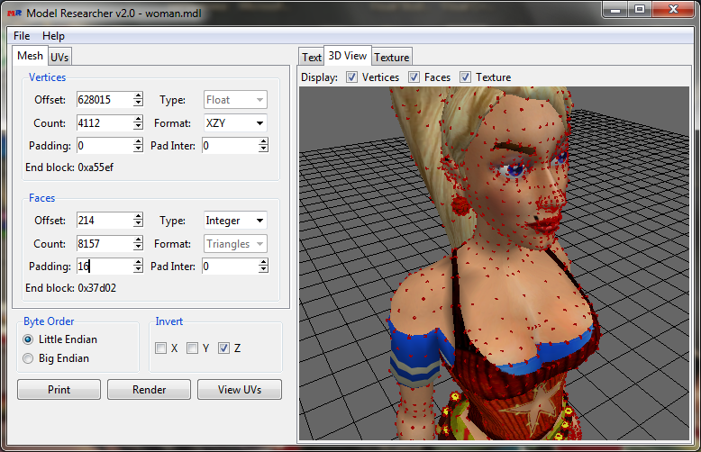
The program window is divided into two parts. There are forms in the left
part, in which settings for file reading is defined, and buttons, which
trigger functions of data output. Form units of data entry in turn are
located in the corresponding tabs. The right part has three tabs, in each
of them there is a definite window of data output/visualization. Above each
window there are parameter settings that determine what data to display.
Let's return to the left part. As you might have already noticed, all
program forms represent units with the same structure. Each parameter
affects reading data from a file.
Offset
is an address(displacement) of start of data unit.
Count
is a number of data segments, which should be read.
Type
is a type of outputting data (Float, Integer, etc).
Format
determines in which format data should be output.
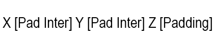
Padding
is a number of bytes, which should be skipped after reading each segment.
Pad Inter
is a number of bytes, which should be skipped after reading each element
(figure) of segment.
End block
outputs the end address of the data unit in hexadecimal, updated
automatically when changing other form fields.
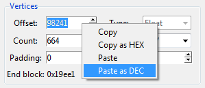
All input field parameters are indicated in decimal numeration system. When
clicking right mouse button on input field, field End block is output in
context menu with operations, which allow pasting and copying of data,
automatically covering them into the correct number system. For instance,
operation “Copy as HEX” copies number from the form into the clipboard,
converting it in sexidecimal notation.
As it has been already mentioned, all input forms of parameters in the
program are similar.
In unit Byte Order byte order is indicated. In majority of cases, little-endian is used. In unit Invert vertices which should be inverted are indicated. When inverting vertex coordinates receive opposite value.
Below there are three buttons: Print, Render and View UVs. Each button can be
applied to such tabs as Text, 3D View, Texture in the right part of the program accordingly. When
clicking on one of the buttons, data is being read by the specified
parameters in the forms and being displayed in the window, which is located
in a specific tab in the right part of the program window.
Button Print outputs read data textually in the field in
the tab Text. Data is being output in the structure
similar to one that is used in Obj format.
Button Render visualizes read data in 3D. Result can be
viewed in 3D View tab.
Button View UVs builds map texture by read data from the
form in tab UVs. Created image is displayed in the tab Texture.
To open the file for reading, one should click in the top menu File ->
Open File.
To save data from forms in file or to upload it, one should click File
-> Open Template, File -> Save Template accordingly.
To export read data in Obj format, one should click in menu File -> Save
OBJ. At the same time, if the texture is uploaded and texture coordinates
are read, together with the file *.obj, file *.mtl will be saved, in which
material with texture is registered. When importing model in 3D graphic
editors, texture will be overlapped automatically.
Structure of 3D formats
The principles of data storage for all models are the same, but data structure for each format are varied. Main volume of any file with 3D model consists of several tables with vertex and face data. These data are enough for building a model. Although, tables with texture coordinates and their indexes, tables with normal vectors, etc can be also met here.
Further we will designate the data in accordance with the Obj format: v – overtaxes, vn – normal vectors, vt – texture coordinates, f – polygons. In the program, the data are output in the same format.
Vertices
Vertex tables store a list with the vertex coordinates in the format of x,
y, z.
v xyz
v 198.6348 30.1159 -70.5724
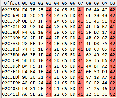
Most commonly coordinates are stored in the form of 4-byte numbers with a
floating point – data type Float. One can recognize these data in a
hex-editor by repeating numbers of 4th byte in the range 40-45 (C0-C5 for
negative figures). Of course, other bytes can be met. Vertices can be also
stored in 2-byte numbers with a floating point of half accuracy – data type
Half-Float.
Faces
Face tables store vertex indexes – some sort of order in which vertices
join, forming polygons (triangles).
f v1 v2 v3
f 1 2 3
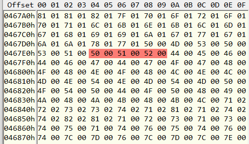
It should be mentioned, that indexing of vertices in the format Obj starts
with1, in the models the minimum index is 0. Indexes can be stored in
groups of three in the form of 4-byte counting numbers (Integer) and 2-byte
(Short). In small models, usually there are a few hundred vertices, the
values of their indexes are small, so this table is well seen. In this
example, one of the triangles is selected, consisting of vertices with
numbers 50,51 and 52.
Texture coordinates
Texture coordinates UV, where u = x, v = y, lie in the range from 0 to 1.
vt uv
vt 0.1547 0.7518
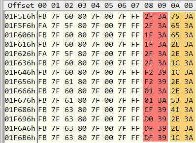
Texture coordinates are stored in 4 byte way (Float), but if texture is
large in size (2048x2048 or 4094x4096), then there is no point in high
accuracy, and they can have Half-Float data type. Here, texture coordinates
are highlighted in red and orange (Half-Float, 2 bytes).
Texture coordinates might use table of faces, but in some cases its own
index table can be used for texture coordinates. Thus the number of
segments in the table of texture indexes should be equal to the number of
segments in the table of faces.
Texture indexes in Obj format are written through a slash after vertex
indexes:
f v1/vt1 v2/vt2 v3/vt3
Normal vectors
For the correct output of the model of the normal vector, one can not look
for it. Model Researcher, like majority of 3D graphic editors calculates
them automatically.
vn xyz
A characteristic feature of the normal is that its length is always equals
1: Sqrt(x2+y2+z2) = 1.
Like texture coordinates, normal vectors can have its own table of indexes.
In Obj format vertex indexes are written through a slash after indexes of
texture coordinates or through two slashes, if indexes of textural
coordinates are lacking.
f v1/vt1/vn1 v2/vt2/vn2 v3/vt3/vn3
f v1//vn1 v2//vn2 v3//vn3
Structures
Not always unites of different data are written separately, they can be mixed up in one table. For instance, from the screenshot with the texture coordinates table one can see, that texture coordinates are written together with other data.
Two types of the most frequently used structures can be distinguished:
1) Sequential
v xyz
v xyz
v xyz
v xyz
...
vn xyz
vn xyz
vn xyz
vn xyz
...
vt uv
vt uv
vt uv
vt uv
2) Coexistence/Mixed
v xyz
vn xyz
vt uv
…
v xyz
vn xyz
vt uv
In both structures order can differ. To read a coexistence structure in Model Researcher correctly, you should set the Padding parameter for padding after each segment.
Source: https://habrahabr.ru/post/263009/
Analysis of 3D model
Let's try to analyze 3D model «cow.mdl».
Download a model
Open the file of 3D model in Model Researcher and in hex-editor.
Vertices
First, you need to find vertices of the model and build point cloud.
Scroll the file in the hex-editor down, until we find the area, which is
fully filled with bytes more than 0. It's hard not to notice its beginning.
It’s clear, that it is not integers data types. Also one can notice, that
value of each 4 byte lies in the range from 40 to 45, from C0 to C5. This
means, that each number takes 4 bytes, Float data type. Well, let's check.
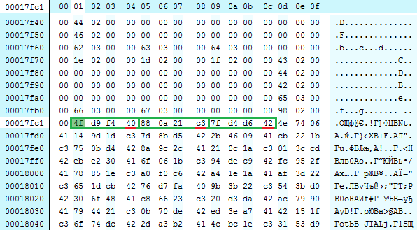
We copy the address of the first byte of this unit – 0x17fc1. We move on to Model Researcher. Parameters for vertex reading are set in the unitVertices in the tab Mesh. In field Offset we paste the copied address. Note that we have copied the address in hexadecimal notation, and the parameters in the program are indicated in decimal. We right-click on the field and choose “Paste as DEC”. In the field Offset our address will be passed in decimal notation. It should be noted, that some hex-editors show addresses in decimal notation, then conversion is not needed.
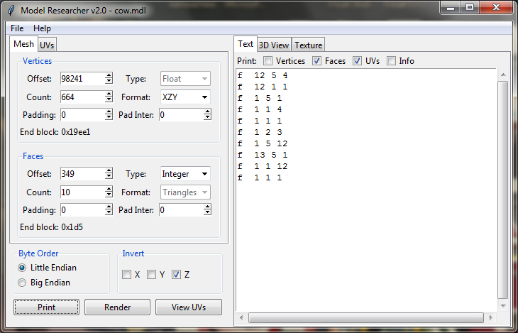
We set the parameter Count. We need to make sure, that these are vertex data, and not something else, therefore we set the number of segments to 10. Then we click on the button Print.
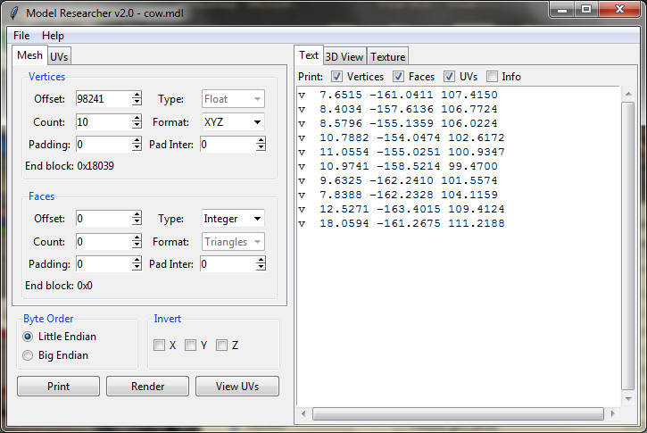
It is very similar to vertex coordinates. Let's try to change the number to 100 and display the read data again by clicking on Print. Having looked through the displayed information, it can be seen, that vertex coordinates are in one table.
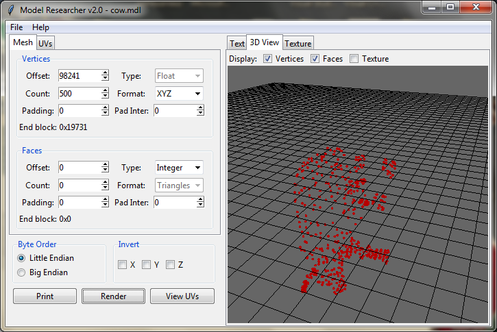
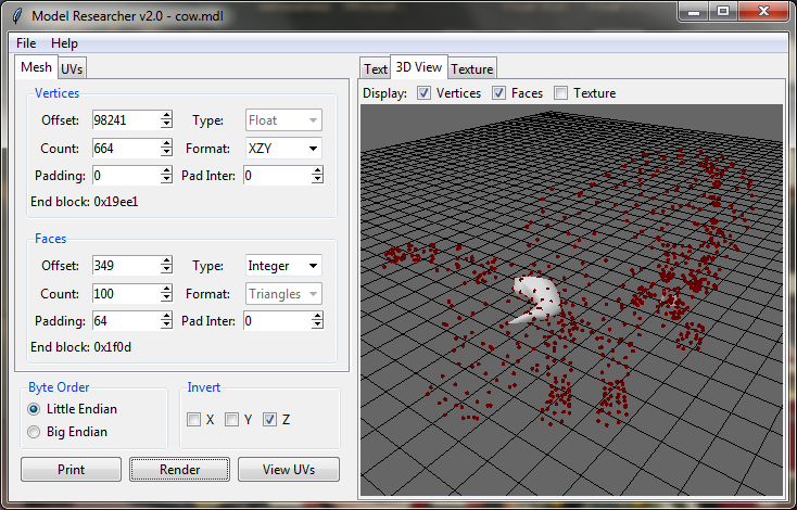
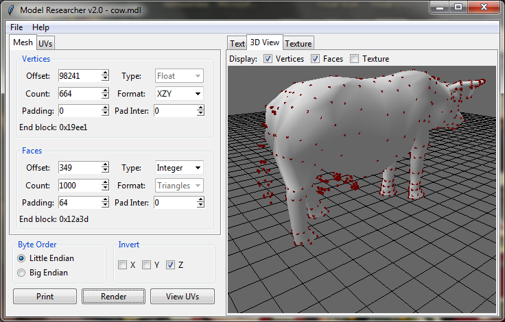
We move on to the tab 3D View in the right part of the program, we press the button Render. In this window we can see visualized data – model itself, simply put. With the left mouse button pressed, you can rotate the camera around, and with the right mouse button pressed, you can move the camera. We can see, that all points are lined up in a certain order, forming some kind of figure. We increase the number of points to 500 and press button Render.
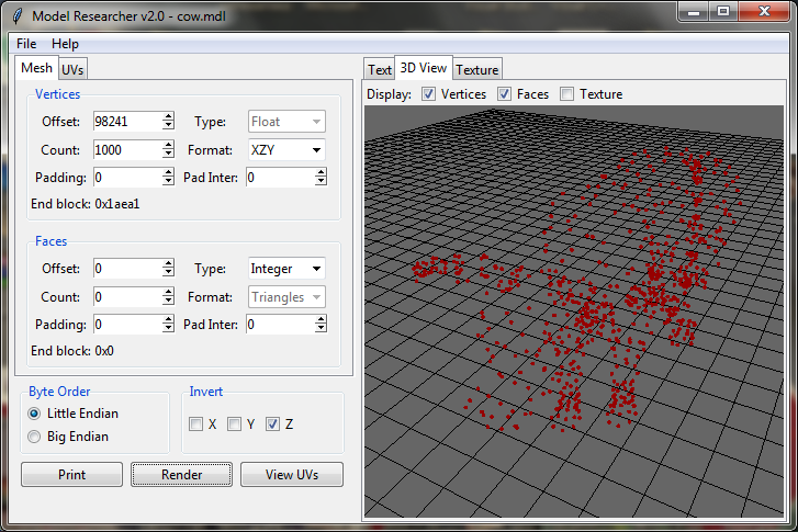
We can take notice of the figure being turned upside down. It is connected with the fact, that the game, from which the file with the model was taken, uses DirectX, and output of 3D graphic in program is achieved through OpenGL. In DirectX Z-coordinate sets the hight, and in OpenGL the hight is set by Y-coordinate. To display the model in the correct way, you need to change the parameter Format in the unit Vertices to XZY and put a check Z in the unit Invert. We increase the number to 1000 and press button Render.
So, we built a point cloud. It is clear that they form a figure. Now we need to know the exact number of vertices, in order not to output more than we need. We move on to the tab Text and press the button Print. Scroll down until we see an abrupt change in the range of values. Data in the end of the unit look more like texture coordinates, than vertex coordinates. We need to know, from which vertex the data were changed. We put a check Info in the top part of output in the parameters Print, having enabled the output of additional information, and press the Print button.
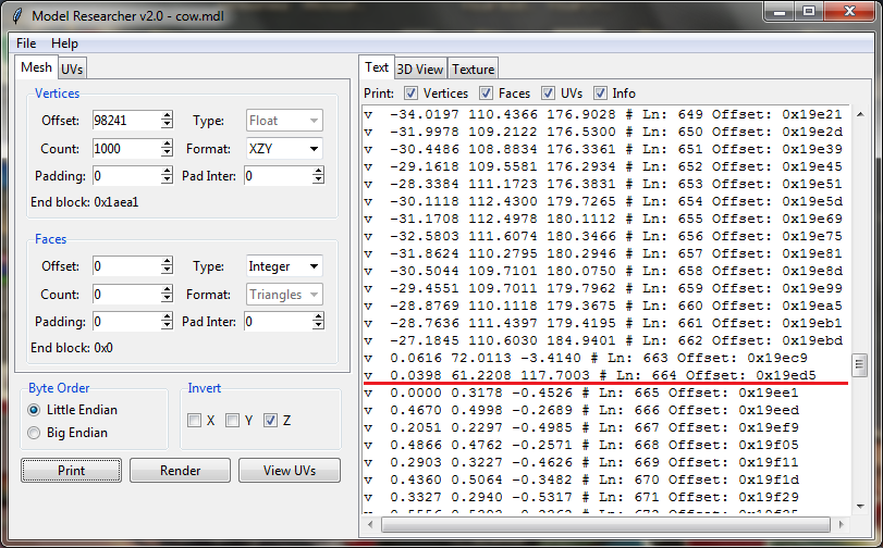
Scrolling down. Now we can see the number of vertex output and its address in hexadecimal form. It is seen that the last coordinate with a large value of 117 is located at the 664 vertex. We paste 664 in the field Count of the unit Vertices.
Faces
After we found the coordinates of the vertices and built a point cloud, we need to find a table with indexes of the face vertices. We move on to hex-editor and scroll up to the very top.
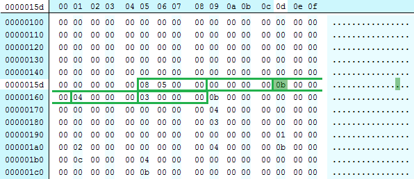
We find the number 0x508 = 1288 after zero bytes (in reverse order). It is a large value for vertex indexes, as we have 664 vertices total. Next comes the number 0. But we stop at 0x0b = 11. We copy address (0x15d) and paste it in the field Offset of the unit Faces with the help of menu “Paste as DEC”, as we did with the address of vertex table. We set the number of polygons, let it be 10. Press the button Print, having deactivate the vertex output before it.
From the output data, we can conclude that the indexes are read incorrectly. There can be no vertices with the same indexes in polygon. Suppose that the first polygon was output correctly. It means, we need to determine how many bytes we need to skip to the second polygon. There is a series of numbers 5, 12, 13 just below. Indexes 5 and 12 are found in the first polygon, and there is also the next index – 13. Is it coincidence? I don't think so. Suppose that the second polygon is read correctly.
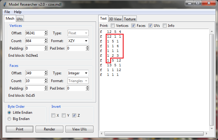
We need to skip numbers highlighted in red. Output data type is Integer,
one number takes 4 bytes. There are 16 numbers total. 16 * 4 = 64. In the Padding box in the Faces block insert 64. Then
we click on the button Print.
Now polygons are more connected with each other, but it is still unclear,
whether the data are read correctly. We increase the number of polygons to
100. Then move on to the tab 3D View and click on the Render button.
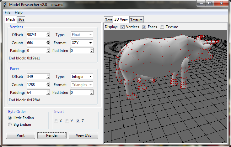
That's right! A part of model was built evidently. We increase the number of polygons to 1000.
Well done! We got a cow. There is no denying, however, that polygons on the tail, ears and udders have not been drawn, this means that there are more than 1000 of them. We increase the number of polygons to 1300 and then let's go to the tab Text and press Print, having turned on the output of additional information before.
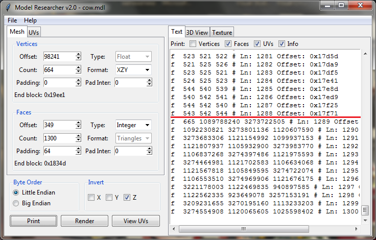
At the very bottom we can see, that after 1289 polygon very large numbers are displayed. According to the number 665, we read the beginning of the table with the vertices (1 is added to each read index of the polygon). In the field Count of the unit Faces we paste 1288, that is the exact number of polygons in this model. We pressRender button and view the result in the tab 3D View.
Texture coordinates
We move on to the textures. Parameters for reading of texture coordinates
and their indexes are set in the tab UVs, let's go there.
Texture coordinates are searched in the same way as vertex coordinates. But
we have already found them, when we output 1000 vertices. This means, that
texture coordinates are right after the vertex coordinates data. We move on
to the tab Mash, copy the address of the end of the vertex
unit by clicking the right mouse button. You can also copy the address in
decimal notation, by selecting “Copy as DEC”. We go to this address in
hex-editor.
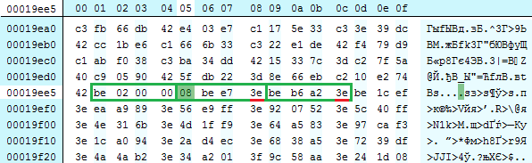
There is a number 0x2be = 702 in the beginning. Apparently, it is the number of texture coordinates in the table. Remember it. And then follow the coordinates themselves. Every forth byte equals 0x3E, hence, we can conclude that these are Float type numbers, take 4 bytes. We copy the address (0x19ee5) of the first number and paste it in the field Offset of the unit UVs. Let's set the number of texture coordinates, which should be read, 10 for starters is enough. We move on to the tab Text and press the button Print.
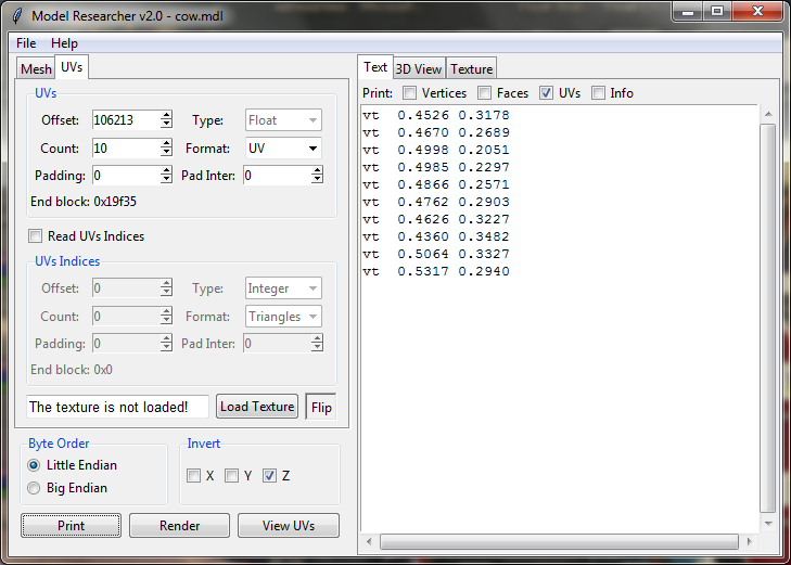
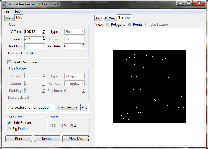
These are indeed texture coordinates. All numbers lie in the range from 0 to 1. We change the number of output segments to 702, this number was at the beginning of the table. You can output, for instance, 703 segments, in order to make sure, that there are exactly 702 texture coordinates. 703 coordinates will look like “vt nan 0.0000”. It is clear, that these data are incorrect.
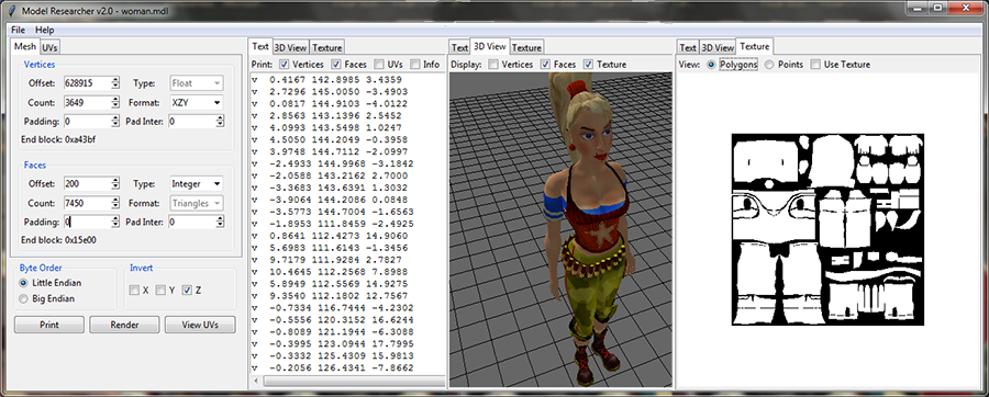
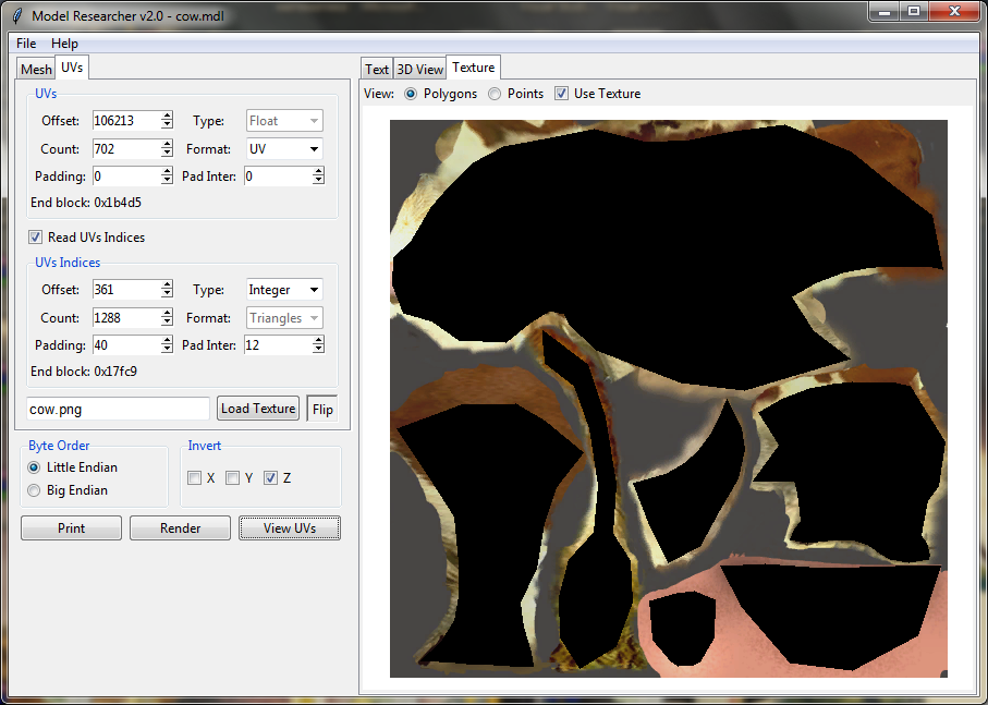
In order to view visualized texture coordinates, we move on to the tab Texture in the right part of the window of the problem. We set View parameter in the top part of the window in Points. We press View UVs button.
Then set the View parameter in Polygons and press View UVs button.
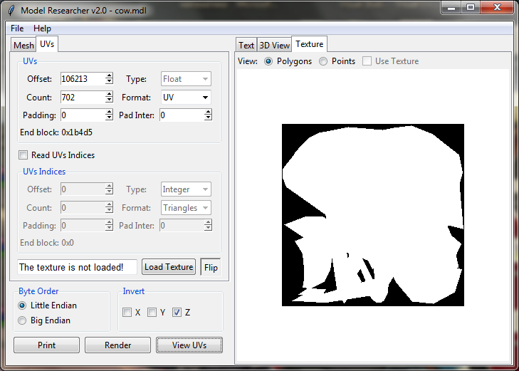
The generated image shows that this format most likely uses a separate
table with texture indexes. But we will check how the texture is overlaid
on the model anyway. Now the table of texture indexes is similar to the
table of faces. It can be seen if we output polygon data textually.
In order to upload texture, you need to click on the Load Texture button and choose the image with texture. If
texture is uploaded, the name of the image will appear in the field near
the button. We set Use Texture parameter above the window
of image output and press the View UVs button.
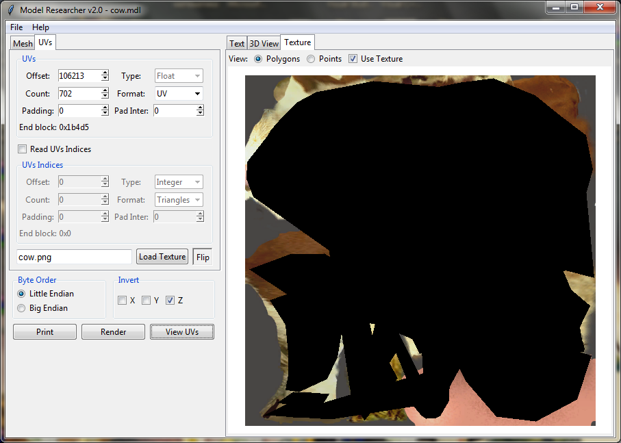
The resulting image confirms once again that a separate table with texture
indexes is used in the format of the model. Parameters for these data
reading are set in the unit UVs Indices. This unit is
blocked by default. For its enabling you need to put a check in Read UVs Indices above this unit.
Immediately we set the number of segments for texture coordinate indexes.
They must be equal to the number of segments in the face table, which is
1288. The search of texture coordinates is no different then the search of
face indexes. So, we make Offset parameter equal to 361,
and Padding parameter equal to 40, and Pad Inter parameter equal to 12. Set these parameters and
then click on the UVs View button.
Now triangles are correctly overlaid on the texture. We move on to the tab 3D View, put a check in Texture and click on the Render button.
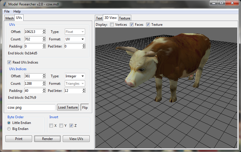
Well done! Now we can export our model in Obj format, having chosen in the menu File -> Save OBJ.
It is worth noting, that it will take time for the data search, especially if it is needed to calculate the necessary padding in mixed structures.